What's new in ZWCAD 2021 SP2
ZWCAD 2021 SP2 has the following new features and enhancements:
| New Features | Description |
| A table in the drawing can be connected to data from a Sheet Data Link or a range of cells from an Excel® file (.xls / .xlsx / .csv) | |
| The path matrix option is available, improving the MATRIX function. | |
| Standard drawing specifications can be created. Different drawings can be standardized with .dws files | |
| The values of the fields in different drawings can be modified all at once. New types of fields can be created | |
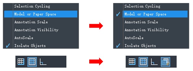
| You can control which icon appears on the status bar. |
| Upgrades | Description |
| Cells can be filled automatically according to certain rules, by dragging the blue grip (fill handle) in the lower right corner of a cell until all cells to be filled are selected. | |
| The path matrix option is available, improving the MATRIX function. | |
| A dialog has been added with new export settings for DGN files. | |
| All OVERKILL procedures can be run from the command line. |
Data link

With the help of these data links, editing tables is now much easier with ZWCAD.
With the help of these data links, editing tables is now much easier with ZWCAD.
A data link can be created in the dialog box when inserting the table or in the Data Link Manager.

Improved matrix.

The long awaited path matrix function is now available, allowing users to evenly distribute selected features along a path using the Divide or Measure method.
What’s more, arrays can now be associative. The size of an associative array can be changed by dragging the blue arrow while its pattern, spacing, and array style remain the same.
Additionally, you can edit arrays in the newly added Array contextual tab. With this contextual tab, it’s easy to make adjustments to a matrix, for example edit its pattern in place, in an intuitive way. You can preview your settings, allowing you to check what you’ve created before saving your changes.

To standardize drawings, you can associate a .dws file with a drawing and check the differences between them. After checking, the drawing specifications can be modified manually or automatically.
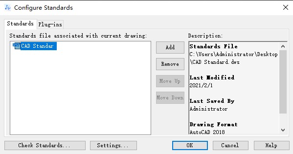
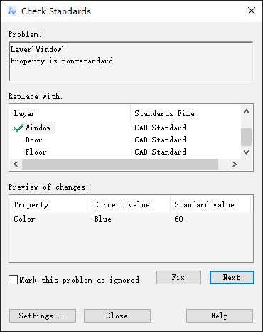
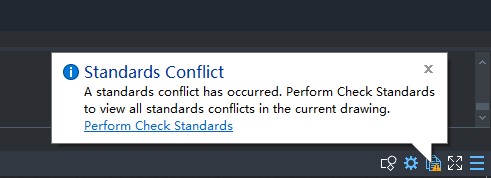
Also, a notification will appear when you create something that does not conform to drawing standards.
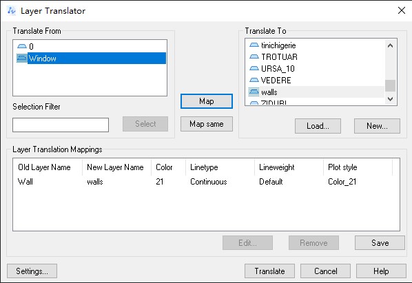
Also, the layer translator available in this function allows you to translate one layer in the current drawing to another.
Propulate
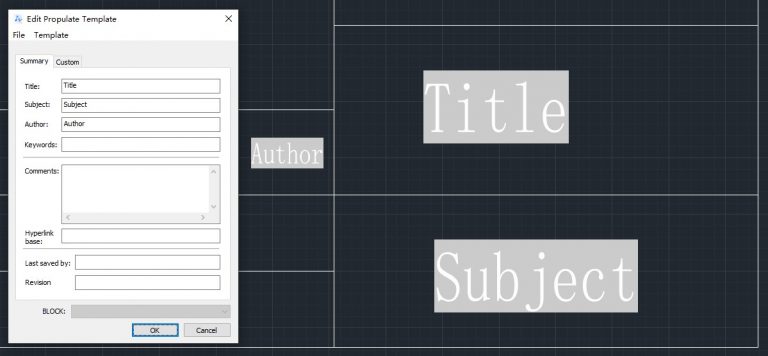
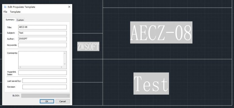
Now that the Propulate tool is integrated into ZWCAD, you can change the values or fields after invoking the Propulate Edit Template dialog box. Modified fields can be synchronized with the current drawing or with other drawings that are not open in ZWCAD.
What’s more, arrays can now be associative. The size of an associative array can be changed by dragging the blue arrow while its pattern, spacing, and array style remain the same.
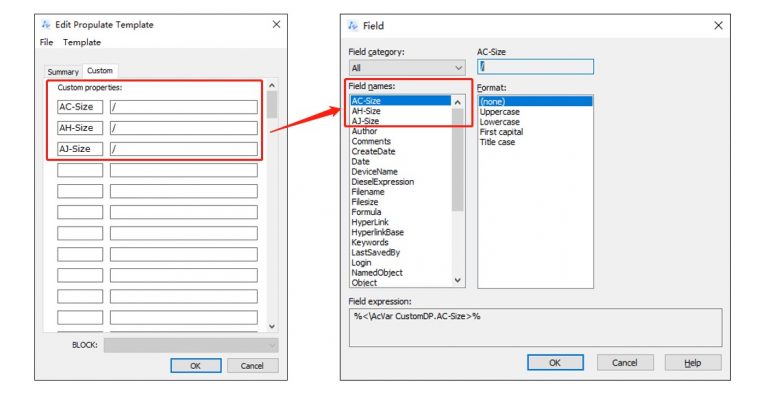
Also, you can create new field types with Propulate . The new field types will be added to the Field dialog, which is very useful when there are different design project requirements.
Status Bar List
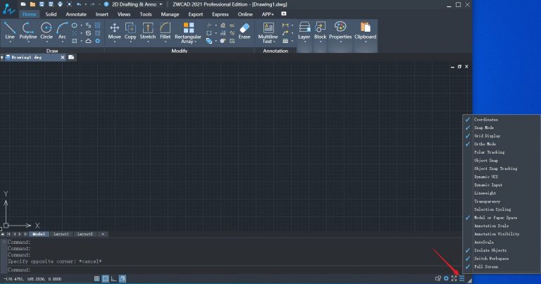
In default mode, all buttons are displayed on the status bar. However, they will probably not all be useful to you.
With the status bar customization, you can now choose to show or hide a certain button on the status bar.
Cell auto-completion in tables
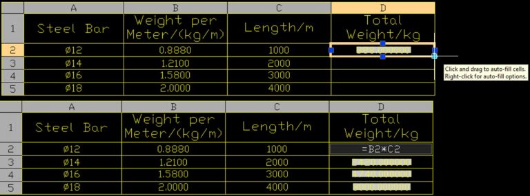
After the availability of table formulas in ZWCAD 2021, the Table function is now even more powerful. In this version, by dragging the blue grip (fill handle) at the bottom right of a cell, you can autocomplete cells according to certain rules such as ascending order or preset formula as shown below.
Precise search
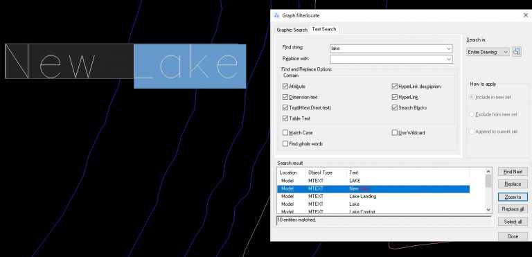
Finding a single entity, for example a word, in a complex drawing can be tricky. However, the improved search function in this version can lead you to the exact position where the word you are looking for is located. This will save you a lot of searching time.
Optimized DGN export
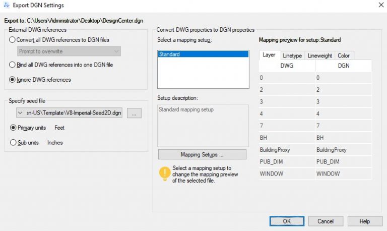
DGN files are commonly used in civil engineering design, such as highway and bridge designs. With DGN export, DWG files can be exported in DGN format, ensuring lossless data exchange between ZWCAD and other CAD solutions, such as MicroStation®.
To export drawings to DGN V7 and V8 files, you can use the DGNEXPORT, -DGNEXPORT, or EXPORT commands.
After choosing the DGN export path, the DGN Export Settings dialog box appears. In this dialog box, you can convert, link, or ignore external DWG references, specify a seed file (MicroStation® template file), and map DWG properties with DGN properties according to certain rules. All these settings will be applied to the DGN file to be exported.
OVERKILL

In the past, when using the REMOVE OVERKILL command ( OVERKILL) , the Remove Duplicate Objects dialog appeared. Now, after using the command “-ELIMINATEOVER”, you can complete all the procedures by following the instructions on the command line.

