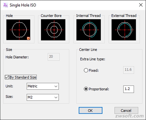
Single holes can be created by standard size that is available in ZWCAD Mechanical, and the length of the center line can be adjusted.
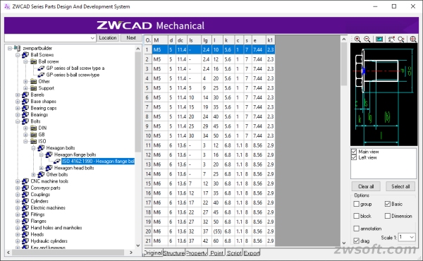
Rearranged Part Library
The part library has been rearranged by the type of parts and standard
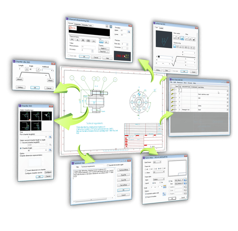
Professional 2D Mechanical Drafting
ZWCAD Mechanical for Manufacturing provides abundant tools such as shaft generator, tolerance dimension, surface texture symbol, globe, and standard parts and bill of materials for 2D mechanical drawing.
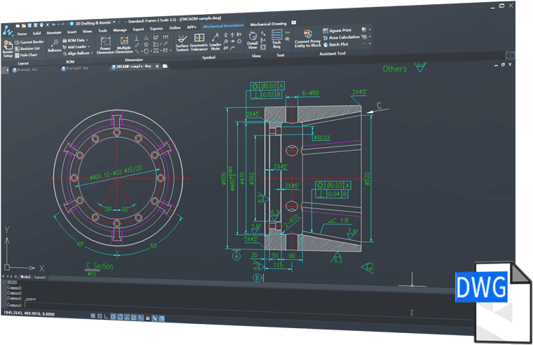
Easy to use and high DWG compatibility
Based on its familiar ZWCAD, high DWG compatibility
Añade aquí tu texto de cabecera
Smart Annotation
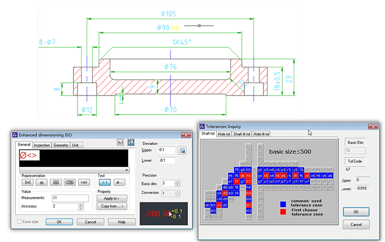
Powerful Dimension
Powerful Dimensioning makes sizing easy with abbreviated dialog boxes that control and expand only those variables that are relevant to manufacturing, as well as integrate tolerance and fit list information.
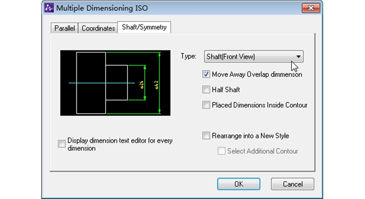
Multiple Dimensions
With Multiple Dimensions, you can create multiple dimensions with minimal input and appropriate spatial ordering, parallel or symmetric elements.
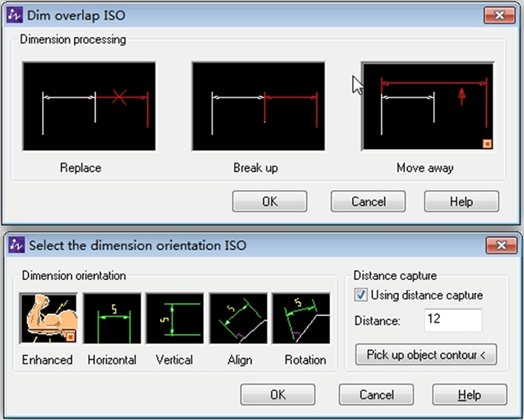
Detect dimension overlap and determine appropriate distance
Overlapping dimensions can be automatically spaced appropriately. The proper distance from the object being sized is determined, making the linear dimensions look neat and clear.
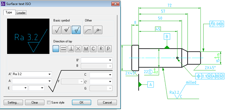
Quick Design with Mechanical Symbols
Mechanical symbols, including surface texture symbols, target and datum identifiers, taper, center hole, and weld symbols, save a lot of time and improve design accuracy.
Smart Globe and BOM
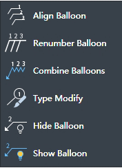
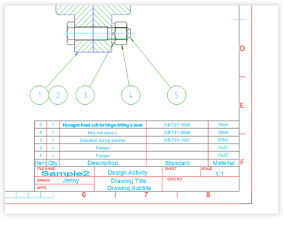
Generate Balloons and BOMs Easily
With ZWCAD Mechanical, you can easily draw, align, and renumber standards-based balloons. It only takes one step to create a bill of materials. In addition, it automatically recognizes the standard parts and summarizes them in BOM.
Associative Globe and BOM
Every change to the balloon would be updated to the bill of materials, making sure the data is always correct and up to date.
Intelligent Drawing Environment
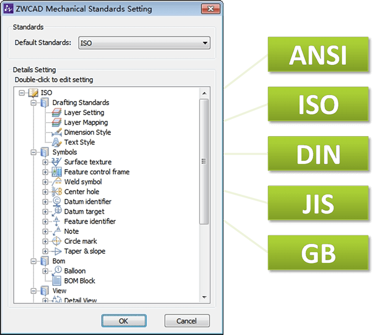
Support of business and international standards
ZWCAD Mechanical supports ISO, ANSI, DIN, JIS, and GB drawing environments, and also provides an easy way to customize company standards.
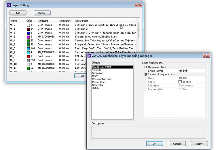
Layer mapping and management
Each mechanical entity such as border, dimension, symbol, etc. would be placed on the default layer with default color and linetype. With layer mapping, the mechanical entity can be placed on a custom layer to match company practices.
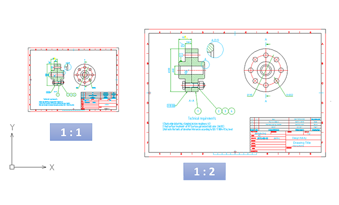
Multiple boundaries and adaptive scaling
ZWCAD Mechanical supports multi-edge drawing with different scales, and the size of annotation objects can be changed according to the edge scale.
Super Edit
Reediting is easy, double click on the objects and then the settings in the dialog will change automatically.
Mechanical Parts and Generator
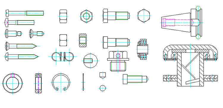
Parts Library
The ZWCAD parts library contains screws, nuts, washers, pins, rivets, springs, bearings, etc. Saves you hours of work by picking up parts straight from the library.
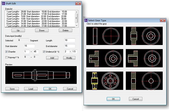
Shafts and Gears
You can create axes and gears by entering the geometric parameters, which greatly speeds up the entire design process.
Extended Drawing Tools for Fabrication
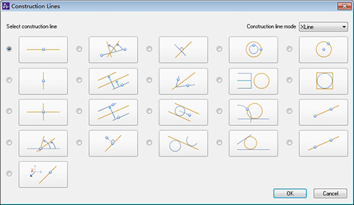
Construction Lines
The program includes a total of 32 options for creating construction lines and 7 options for creating construction circles. Construction lines can be used as a reference to create other objects and make drawing easier.
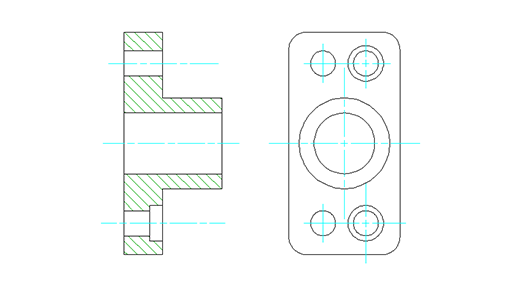
Advanced Central Line
You can add a center line to a circle or rectangle simply by selecting objects. Center lines can be drawn as a single entity or multiple entities.
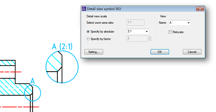
Reusable Detail Tools
Generate the detail view with a few clicks, and it can be updated when a change is made to the geometry.
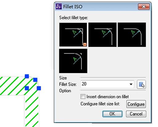
Draw Notches Quickly and Accurately
Technical notch is an essential segment in the mechanical design process, ZWCAD Mechanical offers a variety of process structure construction features, including crack grooves, shaft reliefs, and hole rectifiers.